As we build our knowledge database, we want to share with you all that we know — from design and engineering tips, to manufacturing hardware — , in our mission to #HelpMakersMake. Learn More.
Here is an article written by our engineering team that will guide you on how to factor in the correct requirements for your sheet metal designs. This whitepaper helps describe a set of broad guidelines that you can use while specifying tolerances for your sheet metal parts drawing(s). Essentially, these are in place due to practical limitations of sheet metal forming, shearing and punching. Please note that these tolerances can change from manufacturer to manufacturer and this is generally a broad range of values that we’ve obtained from our experience.
What is shearing, punching and bending?
Shearing
Shearing is used to describe cutting of a sheet metal part. It is usually used in conjunction and/or after a preliminary cutting process such as laser cutting or waterjet cutting, depending on the base material.
The process of shearing itself involves using a sharp hard mandrel to press upon the metal, with a force above its shear strength. This causes the metal edge to be sheared-off. It is not uncommon to have two complementary mandrels imposing the force on the sheet metal part, providing enough force for a clean cut.

Punching
Similar to shearing, punching consists of a hard tool that is pressed onto the work part with a force higher than the shearing force of the material. The process is usually carried out with tools of standard shapes and sizes, such as circles, squares, triangles or other polygons.
The process of punching itself, involves a die, a punch and the work part. The work part is sandwiched between the die and the punch. The tool (usually made of HSS or carbide) is sharply brought down and punches out the shape desired (called a slug).

Bending (Forming)
Sheet metal pieces are usually cut, punched and then bent (order may vary depending on the features). Bending involves a punch, a die and the work part. The sheet meal work part is sandwiched between the die and the punch. The punch is brought down sharply using a hydraulic ram, to bend the sheet metal part in the desired shape.

Dimensions and Tolerances
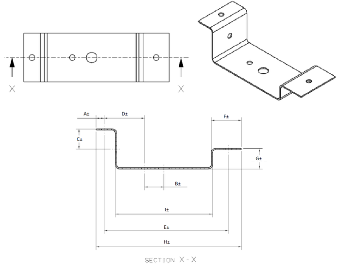
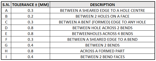
To better understand how to factor in the dimensional tolerances of each of these processes (shearing, punching and bending), here’s a sample part that we’ve designed that has all the kinds of holes and bends that you can possibly replicate in your part! The dimensional callouts display the measurement and the table below provides the tolerance values that must be taken into account while designing the part and assembly. The tolerance values indicate the degree to which a feature can be controlled, however for complex assemblies, it may be necessary to do a stack up-analysis to determine the allowances.
…
About Factorem:
Factorem is Southeast Asia’s first on-demand, one-stop portal to custom manufacturing. We are making hardware procurement and prototyping processes smarter, faster, and more efficient. Through our trusted partner network, we help hardware teams get high quality customized parts at their optimal price and lead time, alongside DFM feedback. Our partners’ capabilities include CNC Machining, Sheet Metal Fab, 3D Printing and more.
Drop us a message at hello@factorem.co — we’re happy to help!
…
Citations:
C. (n.d.). Overviews. Retrieved November 30, 2020, from https://www.custompartnet.com/wu/sheet-metal-forming
C. (n.d.). Sheet Metal Cutting. Retrieved November 30, 2020, from https://www.custompartnet.com/wu/sheet-metal-shearing
